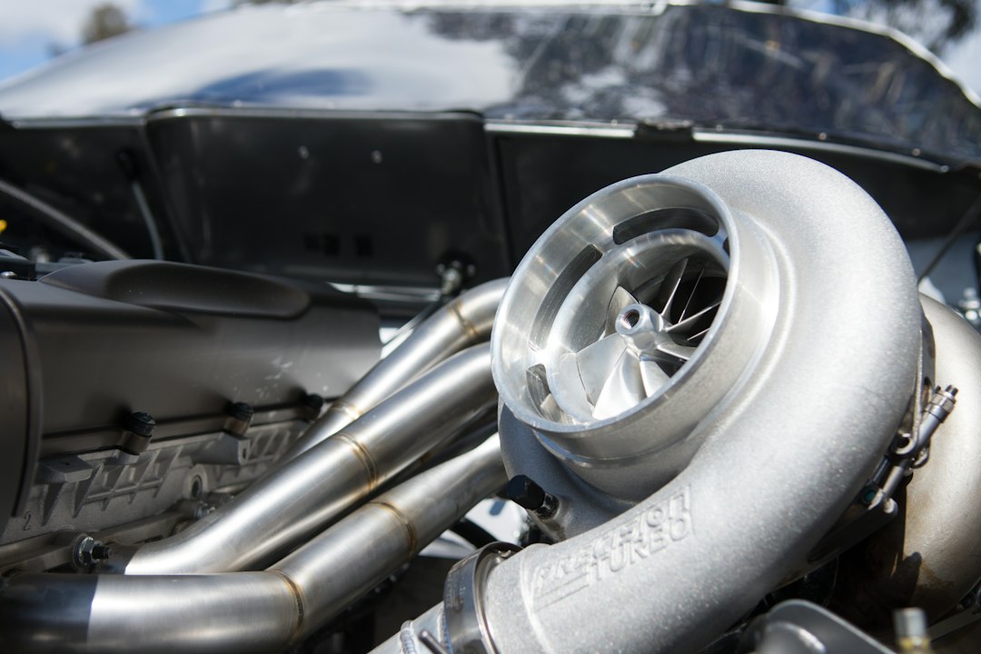
The compressor side draws air through the inlet, compresses it, and sends it toward the intercooler and intake manifold. The turbine side extracts energy from exhaust gas and transfers that energy through the shaft to the compressor. Both sides must suit the engine. A compressor with substantial high-rpm airflow capacity may support strong power near the top of the rev range, yet produce slower response on a smaller engine with limited exhaust flow at low speed. The next gen 8385 range should therefore be examined through its full specification rather than treated as a promise of one fixed driving experience.
Turbo response and maximum airflow are separate characteristics. Response describes how quickly shaft speed and boost rise after throttle opening and increased engine load. Maximum airflow concerns how much air the compressor can move within an efficient operating range. A road car may benefit from useful torque during ordinary gear changes, while a track car with a close-ratio transmission may spend more time above 5,000 rpm and tolerate later boost. Boost threshold is also a system result, not a number belonging to the turbo alone. Engine displacement, compression ratio, cam timing, exhaust manifold volume, gear, and load all affect the point at which positive pressure becomes useful.
Housing selection changes the compromise. The A/R ratio compares the housing cross-sectional area with its radius from the turbine centerline. A smaller housing can increase exhaust-gas velocity and may support earlier turbine acceleration, although it can also increase restriction at high flow. A larger housing may reduce restriction for a high-rpm engine while moving the useful response later in the rev range. The right comparison is between the vehicle’s actual duty cycle and the intended housing, not between one A/R number and another in isolation. A street-driven six-cylinder and a drag engine can need different housings even with related turbo hardware.
Mirror-image configurations are functional packaging options, not merely cosmetic variations. On a twin-turbo engine, opposing layouts can place compressor outlets, turbine inlets, or downpipes in positions that simplify routing or improve symmetry. Fitment still has to be checked on the actual engine. Measure clearance around the valve covers, frame rails, steering shaft, brake hardware, and radiator before ordering fabricated parts. Mark the planned oil drain angle as well, because a drain that cannot run downward can create installation and service problems. Confirm coolant fittings, wastegate access, charge-pipe paths, and room to remove the turbo without dismantling half the engine bay.
Wastegate control determines how exhaust energy is managed once the turbo approaches the intended boost level. The gate, actuator, boost-control plumbing, and calibration must work together. A leak, weak actuator setup, poorly placed reference line, or unsuitable control strategy can lead to unstable pressure, boost creep, or an unexpectedly slow rise. The pressure shown near the compressor outlet is not necessarily the pressure reaching the intake valves. Intercooler and charge-pipe restriction can consume part of that pressure, especially if the core is undersized or the piping has restrictive bends. Logging manifold pressure, intake temperature, engine speed, and wastegate duty gives a more useful picture than watching one gauge.
Supporting hardware sets the practical limit of the installation. Injector capacity, pump delivery, fuel pressure control, engine strength, exhaust manifold design, intercooler volume, sensors, and engine management all deserve review before the turbo arrives. A useful workshop habit is to print the turbo drawing and mark flange locations, inlet diameter, outlet orientation, and drain positions against the vehicle’s measured dimensions. Another is to write down the intended rpm range and gear used for testing, since a road pull in third gear can produce a different impression from a launch or a high-speed circuit lap. These small records reduce rework and expose mismatches early.
The final decision should reflect how the car is driven, not only the largest airflow figure in a catalog. A commuter may need predictable low-speed behavior, manageable exhaust temperature, and a calibration that remains stable through repeated traffic use. A competition build may accept later response for stronger airflow at high engine speed, provided the engine, fuel system, cooling arrangement, and control hardware are prepared for it. Review compressor-map operating points with the expected displacement and rpm, then check turbine housing and wastegate details against the exhaust design. Use the turbo sizing reference as one source of specifications, while verifying dimensions and supporting requirements against the actual vehicle.